
Drilled Pier Foundations: How They Work in Clay and When They're Used
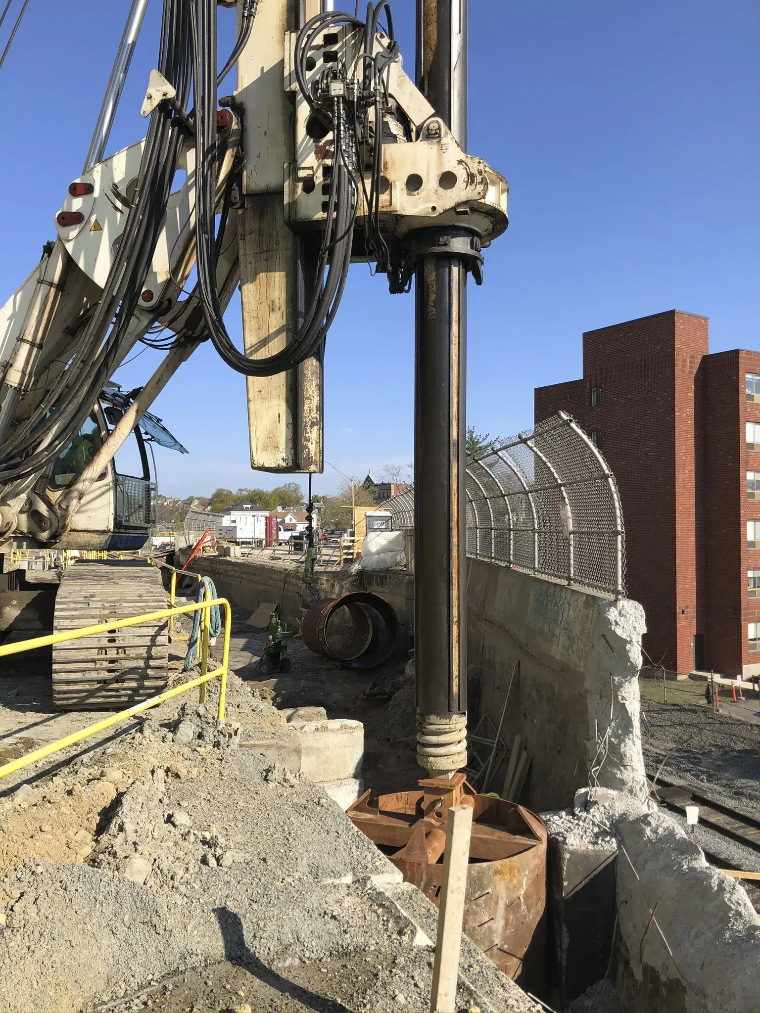
A rotary rig advancing a foundation shaft through a short steel surface casing. (Photo: MassDOT · Public domain (as stated on the Wikimedia Commons file page))

A drilled pier foundation is a reinforced concrete column cast in a hole drilled into the ground, usually down to a stiffer soil or rock layer. It carries the building's load through friction along its sides and bearing at its tip. In North Texas, drilled piers are a common deep foundation for commercial and municipal buildings. They let the structure bypass the expansive clay near the surface, and they have to be designed so that clay can't lift them.
The same foundation goes by several names. FHWA's drilled shaft manual (GEC 10) notes that drilled shafts "are also referred to by other names, including drilled piers, caissons, cast-in-drilled-hole piles... and bored piles." On a building plan in Texas you'll usually see "drilled piers" or "drilled shafts." They mean the same thing.
How a drilled pier carries load
GEC 10 describes the basic sequence in four steps: excavate the hole while keeping it stable, clean the hole, place the reinforcement and concrete, and finish the top to connect to the structure. The finished pier "supports axial forces through a combination of side shear and end bearing resistance." Because it's a large-diameter reinforced member, it also resists lateral and overturning loads well.
On a typical commercial building, the piers sit under columns and at intervals along the walls. Reinforced concrete grade beams span between them and carry the walls. The floor is either a slab on grade or a structurally suspended slab, depending on how much movement the soil can produce. (We cover the suspended-floor side, and what it means for plumbing, in our article on suspended foundations.)
Why drilled piers are common on North Texas clay
Much of the region sits on the Blackland Prairie and Grand Prairie. NRCS describes the Houston Black clay found there as very deep soil formed over calcareous mudstone, with dry-season cracks 0.5 to 4 inches wide reaching a foot or more down. Related soils in the same area sit over weathered shale or chalk. That profile suits drilled piers. The rig drills through the clay, and the pier bears in the shale or limestone below, where moisture barely changes.
GEC 10 is direct about the two design problems expansive soil creates. First, shafts have to extend "below depths where substantial volume changes may occur," meaning below the zone of seasonal moisture change, often called the active zone. Second, they must be designed to resist uplift, because swelling clay grips the upper part of the shaft and pushes it upward. GEC 10 notes uplift matters most for lightly loaded foundations and may require "substantially greater reinforcing steel than would be needed to support other loads."
The 2021 IBC says the same in code language. Section 1808.6.1 requires that foundations "extending into or penetrating expansive soils shall be designed to prevent uplift of the supported structure." They must also either resist the forces from soil volume change or be isolated from the expansive soil.
Designers use three tools here:
- Embedment below the active zone, deep enough that the anchorage below outweighs the uplift above
- Full-length reinforcement sized for the tension that swell can put on the shaft
- Void space under grade beams. GEC 10 says members connecting shafts near grade "should be designed and constructed to have sufficient clearance above the ground surface to avoid uplift from swelling ground." On buildings the gap is usually formed with a void form placed under the beam before the pour, leaving space the clay can swell into
Some designs also isolate the upper shaft with a liner. GEC 10 reports that two concentric pressed-fiber tubes separated by asphalt reduced skin friction in expansive soil "by as much as 90 per cent" compared with no liner.
What about bells?
A belled pier has an enlarged base, cut with an underreaming tool at the bottom of the hole. The bell spreads the end-bearing load and adds anchorage against uplift. GEC 10's history section notes that early Texas contractors used augered holes and "sometimes tools were employed to rapidly cut an underream or bell." Bells need a bearing layer that will stand open without caving and without groundwater coming in. They also take more inspection, because the inspector has to confirm the bell diameter. Whether a bell is worth it, or a straight shaft with deeper embedment does the job, is a design call made from the borings.
Drilled pier vs. driven pile vs. spread footing
| Drilled pier (drilled shaft) | Driven pile | Spread footing | |
|---|---|---|---|
| How it's built | Hole drilled, cage set, concrete placed in the hole | Steel or precast concrete section hammered or vibrated in | Shallow excavation, reinforced pad cast below grade |
| Where it bears | Stiff soil or rock at depth, plus side friction | Side friction and tip resistance at depth | Near-surface soil |
| Noise and vibration | Low (GEC 10 lists this as an advantage near existing structures) | High | Low |
| Bearing check during install | Bearing layer can be inspected directly. GEC 10 notes there is no direct measure of capacity as with driving resistance | Driving resistance gives a field indication of capacity | Inspector checks the bearing soil before the pour |
| Fit on expansive clay | Good when designed for uplift with void forms under grade beams | Possible, but must also resist swell uplift | Footings in the active zone move with the clay unless the soil is treated or removed |
| Sensitive to | Groundwater, caving sands, construction quality | Obstructions, hard layers, nearby vibration-sensitive buildings | Soil moisture change, poor fill |
| Where it tends to fit | Heavy or movement-sensitive buildings on clay over shale or limestone | Deep soft soils where a field capacity check during driving is valuable | Light structures where borings show low swell or the clay is treated or replaced |
GEC 10 lists the main drawbacks of drilled shafts plainly: construction "is sensitive to groundwater or difficult drilling conditions," performance can depend on the construction method, and the cast-in-place concrete "requires careful construction, QA/QC."
Dry holes, casing and slurry
Most piers in North Texas clay are drilled "in the dry." The clay stands open, the hole stays dry, and the concrete goes in soon after drilling. GEC 10 describes the concrete for a dry hole as a high-workability mix with "typically 6 to 8 inch slump," placed by free fall with a centering device so it doesn't hit the cage or the sides of the hole.
When the borings show sand seams or groundwater, the contractor may need temporary steel casing to hold the hole open, or a drilling fluid (slurry) with concrete placed by tremie from the bottom up. Your geotechnical report should say where water and caving soils were found. GEC 10 puts these items in the site investigation for a reason: groundwater, permeability, rock hardness and obstructions decide how the shafts get built.
What should be checked before concrete goes in
The 2021 IBC requires special inspection of cast-in-place deep foundations. Table 1705.8 calls for continuous special inspection to:
- Inspect drilling operations and keep complete records for each element
- Verify location and plumbness, and confirm element diameters, bell diameters (if any), lengths, embedment into bedrock and adequate end-bearing strata. Record concrete volumes
- For concrete elements, perform the concrete tests and inspections of Section 1705.3
On bottom cleanliness, GEC 10 cites a typical specification of no more than three inches of loose material just before concrete. Where base resistance in rock is counted in design, 50 percent or more of the base should have no more than half an inch. Some agencies limit it to 1-1/2 inches for shafts that rely heavily on end bearing.
A practical pre-pour checklist for the owner's team:
- Bearing layer reached and confirmed against the boring logs, with embedment measured from the top of that layer
- Diameter, depth and plumbness recorded for each pier
- Bottom cleaned to the spec, and no water standing in a hole designed as "dry"
- Cage length, bar size and spacers match the drawings, with uplift steel running the full length where specified
- Concrete placed promptly after the hole is cleaned and inspected, before water or sloughing soil can collect
- Void forms set under grade beams to the specified depth and protected from rain before the pour
How long can a drilled pier be?
The code puts a limit on uncased piers. IBC §1810.3.5.2.2 says an uncased cast-in-place element must be at least 12 inches in diameter, and its length "shall not exceed 30 times the specified diameter." It can be longer if a registered design professional knowledgeable in soil mechanics and deep foundations supervises the design and installation and reports to the building official. On large projects, GEC 10 notes that transportation shafts commonly run up to 200 feet deep. Building piers in North Texas are usually far shorter, set by where the bearing layer is.
Planning drilled piers for your project
Isbell Engineering Consultants provides geotechnical foundation recommendations for shallow and deep foundations, including drilled shafts, and structural design of the foundations that sit on them. Having both in one firm means the pier depths, uplift steel and grade beam voids come from the same understanding of the soil. Construction phase services are available as well. Learn more on our geotechnical engineering services and structural engineering services pages, or send your site plan and building information through the contact page.
Frequently asked questions
What is a drilled pier foundation?
It's a cast-in-place reinforced concrete column formed in a drilled hole. It transfers building loads to deeper, stiffer soil or rock through side friction and end bearing. It's also called a drilled shaft, caisson or bored pile.
How deep are drilled piers in North Texas?
There's no standard depth. The geotechnical engineer sets it from the borings, based on where the bearing layer is and how deep the seasonal moisture change goes in the clay. The pier has to be anchored deep enough below that zone to resist uplift from swelling soil.
What is the difference between a drilled pier and a pile?
A drilled pier is cast in a hole that's been drilled and cleaned, so the bearing layer can be inspected. A driven pile is a manufactured section hammered into place, and its driving resistance gives a field check of capacity. Drilled piers make far less noise and vibration.
What is a grade beam?
A grade beam is a reinforced concrete beam at or near ground level that spans between piers and supports walls. On expansive clay, grade beams are usually formed over a void form so swelling soil can't push up on them.
Are belled piers still used?
Yes, where the bearing layer stands open and dry. A bell adds end-bearing area and uplift resistance, but it's harder to build and inspect than a straight shaft, so the choice depends on the borings.
Sources
- FHWA GEC 10, Drilled Shafts: Construction Procedures and Design Methods (FHWA-NHI-18-024, 2018)
- 2021 International Building Code as adopted in Texas, Chapter 18 Soils and Foundations (§1808.6, §1810)
- 2021 International Building Code as adopted in Texas, Chapter 17 Special Inspections and Tests (§1705.8, Table 1705.8)
- USDA NRCS Official Soil Series Description, Houston Black
- FHWA Geotechnical Engineering, Foundations program page
Image credits
- Drill rig with a Kelly bar and auger tool drilling a drilled pier foundation through a steel surface casing. Photo: MassDOT · Public domain (as stated on the Wikimedia Commons file page)
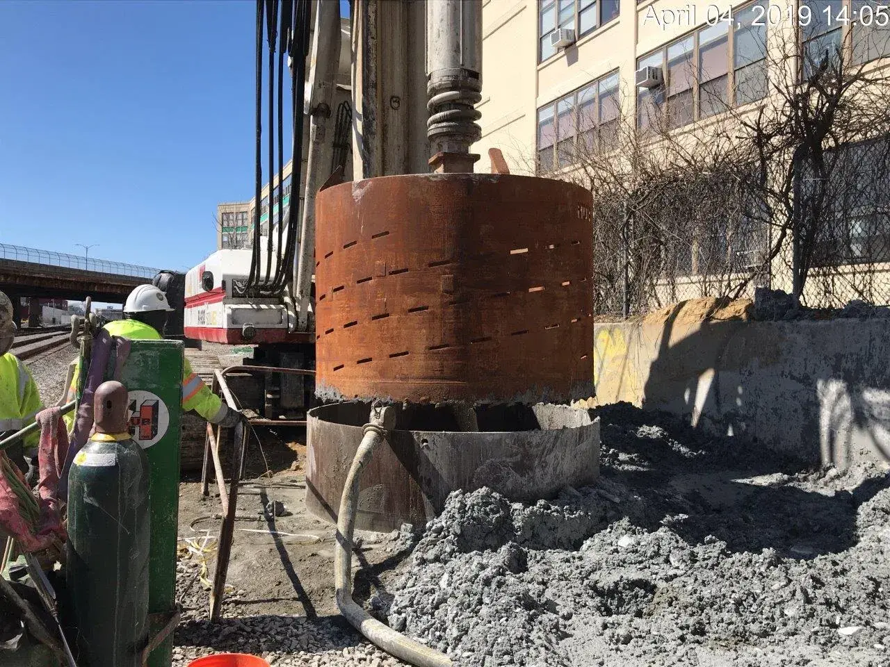
- Cleanout bucket lifted out of a cased drilled shaft with spoil piled beside the casing. Photo: MassDOT · Public domain (as stated on the Wikimedia Commons file page)

Related articles
Copyright © 2026 Isbell Engineering Consultants - All Rights Reserved.
Made & Managed by North Texas Business Solutions